Pipe to Pipe Intersection Development Example
Pipe-to-pipe intersections are commonly used in piping systems, pressure vessels, ducting systems, process equipment, and industrial fabrication projects. To fabricate an accurate branch connection, the cutting profile of the branch pipe must match the surface of the header pipe.
This example demonstrates a typical pipe-to-pipe intersection development and shows how the generated layout can be used for fabrication marking and cutting operations.
Problem Statement
A fabrication shop needs to prepare a branch pipe connection between two cylindrical pipes.
The objective is to generate the branch pipe cutting profile so that the branch pipe fits accurately onto the header pipe before welding.
Given Dimensions
Assume the following dimensions:
- Header Pipe Diameter = 600 mm
- Branch Pipe Diameter = 300 mm
- Branch Angle = 90°
- Number of Development Divisions = 12
The branch pipe intersects the header pipe at right angles and both pipe centerlines intersect at the center.
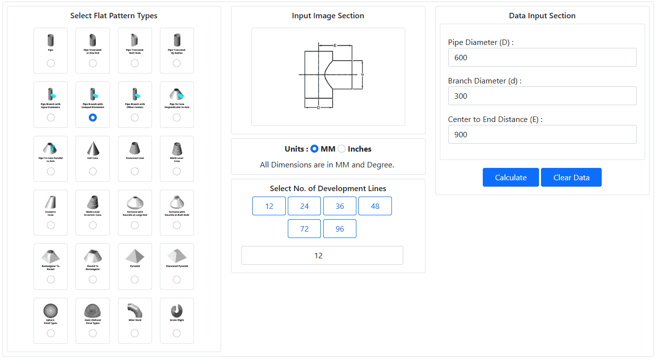
Input Data
The following values are entered into the Let’sFab Pipe Flat Pattern Development Calculator:
- Header Diameter = 600 mm
- Branch Diameter = 300 mm
- Center to End Distance = 900 mm
- Branch Angle = 90°
- Development Divisions = 12
Development Calculation Overview
For a pipe-to-pipe intersection, the branch pipe circumference is divided into equal development divisions.
True-length calculations are then performed for each division point to determine the intersection profile between the branch pipe and the header pipe.
The calculated values generate the fish-mouth cutting profile required for fabrication.
The resulting profile contains a series of layout points that can be marked directly onto the branch pipe or transferred to a flat plate for cutting.
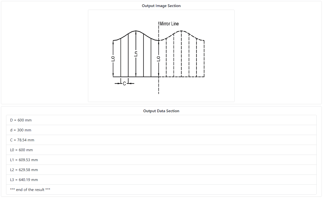
Generated Development Results
The calculator generates:
- Branch Cutting Profile
- Development Division Lengths
- Fabrication Layout Data
These dimensions can be used directly for workshop layout marking and fabrication operations.
Fabrication Procedure
After obtaining the calculated dimensions:
- Mark the development points on the branch pipe.
- Connect the generated points smoothly.
- Cut the profile using plasma, laser, oxy-fuel, or manual cutting methods.
- Grind and finish the edge if required.
- Position the branch pipe onto the header pipe.
- Verify fit-up before welding.
A properly developed intersection profile minimizes fitting time and improves weld quality.
Benefits of Using a Pipe Development Calculator
Compared with manual triangulation methods, the calculator provides:
- Faster calculations
- Improved accuracy
- Reduced layout errors
- Better fit-up quality
- Lower fabrication costs
- Reduced material waste
This becomes especially valuable when working with unequal diameter or offset pipe intersections.
Try the free Pipe Branch Calculator
Explore Let’sFab Premium Software
Typical Applications
Pipe intersection developments are widely used in:
- Process piping systems
- Pressure vessels
- Storage tanks
- HVAC systems
- Cyclones
- Dust collection systems
- Industrial ducting
- Chemical plants
- Oil and gas facilities
- Power plants
Frequently Asked Questions
What is a fish mouth layout?
A fish mouth layout is the curved cutting profile generated on a branch pipe so that it fits accurately onto the header pipe.
Why are development divisions used?
Development divisions break the pipe circumference into equal segments to generate accurate layout points for the intersection profile.
Can the generated dimensions be used directly for fabrication?
Yes. The calculated dimensions can be used for layout marking, profile cutting, and fabrication planning.
What happens if I increase the number of development divisions?
Increasing the number of development divisions generally improves the accuracy of the generated profile.
Can this method be used for unequal diameter pipe intersections?
Yes. The same development principles apply, although the resulting profile becomes more complex.
Related Resources
- How to Calculate Pipe Flat Pattern Development
- Pipe to Pipe Intersection Development
- Pipe to Cone Intersection Development
- Pipe Development Formula
- Pipe Branch Calculator
- LetsFab Premium Flat Pattern Calculator
- Free Sheet Metal Development eBook