Square to Round Transition Development Example
Introduction
A square-to-round transition is one of the most common sheet metal fittings used in HVAC ducting, dust collection systems, industrial ventilation, process piping, and material handling equipment. It connects a square or rectangular opening to a round duct while maintaining smooth airflow and minimizing pressure losses.
This article presents a practical square-to-round transition development example and explains the process of creating the flat pattern required for fabrication.
If you are unfamiliar with transition layouts, dimensions, and terminology, read our guide on How to Read and Create Transition Flat Pattern Layout Drawings before proceeding.
Given Dimensions
For this example, assume the following dimensions:
| Parameter | Value |
|---|---|
| Square Side Length | 400 mm |
| Round Diameter | 300 mm |
| Transition Height | 500 mm |
| Seam Allowance | 15 mm |
| Material Thickness | 2 mm |
These dimensions represent a typical HVAC transition fitting used to connect a square duct to a round duct.
Step 1: Define the Transition Geometry
The lower section consists of a square opening measuring 400 mm × 400 mm.
The upper section consists of a round opening with a diameter of 300 mm.
The vertical distance between the two profiles is 500 mm.
The objective is to develop the sheet metal pattern that can be cut and formed into the transition piece.
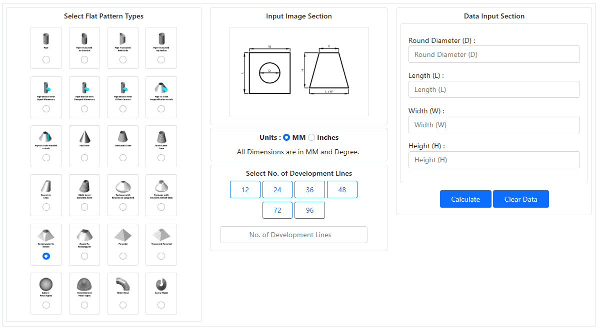
Step 2: Divide the Round Profile
To develop the transition accurately, the round profile is divided into equal segments.
Each division point becomes a generator line connecting the round profile to corresponding locations on the square profile.
Typical layouts use:
- 12 divisions
- 24 divisions
- 36 divisions
- 48 divisions
Increasing the number of divisions improves pattern accuracy and provides smoother transition geometry.
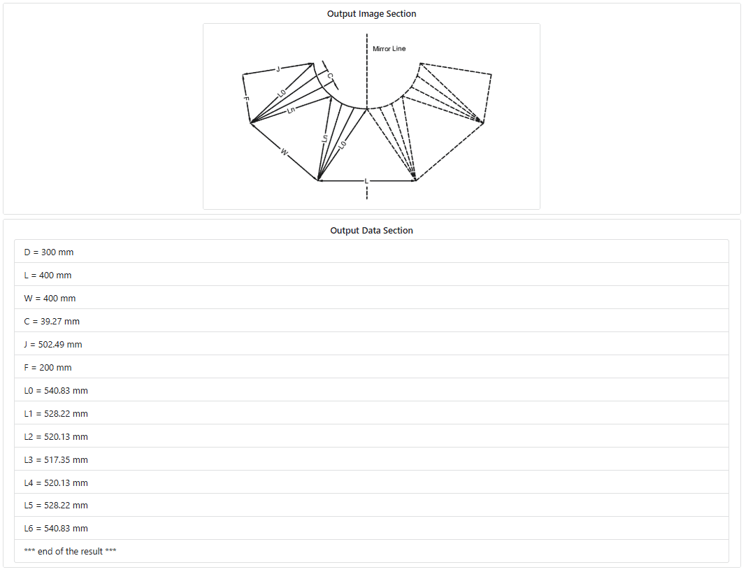
Step 3: Determine Generator Lengths
Each generator line has a unique true length because the distance between the square and round profiles changes around the transition.
These true lengths are typically identified as:
- L0
- L1
- L2
- L3
- …
- Ln
The lengths are calculated using triangulation methods or generated automatically by a transition development calculator.
These values form the basis of the flat pattern layout.
Step 4: Create the Flat Pattern Layout
Using the calculated true lengths:
- Draw the base reference line.
- Mark the circumferential distances along the layout.
- Transfer each true length to its corresponding division point.
- Connect the resulting points with a smooth curve.
- Add seam allowance if required.
The completed layout represents the exact shape required for cutting the sheet material.
Step 5: Add Fabrication Allowances
Before cutting the material, additional allowances may be required for:
- Lock seams
- Pittsburgh seams
- Weld joints
- Lap joints
- Hemmed edges
The allowance value depends on the fabrication method and material thickness.
For this example, a 15 mm seam allowance is added along the joining edge.
Step 6: Cut and Form the Transition
After transferring the developed pattern to the sheet material:
- Cut the flat pattern.
- Form the transition using rolling and bending operations.
- Join the seam by welding, riveting, or lock forming.
- Verify dimensions before installation.
The finished component should match the original square and round dimensions specified in the design.
Common Mistakes in Square-to-Round Development
Incorrect True Length Calculations
Even small errors in true length measurements can cause poor fit-up during assembly.
Unequal Division Spacing
Inconsistent division spacing produces distorted transition geometry.
Missing Seam Allowance
Failure to include seam allowance may result in undersized fabricated parts.
Inaccurate Layout Transfer
Errors during marking and cutting can affect the final shape and dimensional accuracy.
Benefits of Using a Transition Development Calculator
Manual development methods can be time-consuming, particularly for complex transitions.
A Transition Development Calculator helps:
- Generate accurate flat patterns
- Calculate true lengths automatically
- Reduce layout errors
- Save engineering time
- Improve fabrication accuracy
For regular fabrication work, calculator-generated developments provide a faster and more reliable solution than manual drafting methods.
Try the free Transition Development Calculator
Explore Let’sFab Premium Software
FAQ Section
What is a square to round transition?
A square to round transition is a sheet metal fitting used to connect a square duct or opening to a round duct while maintaining smooth airflow.
How do you calculate a square to round transition development?
The development is calculated using triangulation methods that determine the true lengths of generator lines between the square and round profiles.
Why are true lengths important in transition development?
True lengths ensure the flat pattern accurately represents the three-dimensional transition shape, preventing fabrication errors.
Can a transition development calculator generate flat patterns automatically?
Yes. A transition development calculator can automatically calculate true lengths, circumferential distances, and flat pattern dimensions for fabrication.
What industries use square to round transitions?
Square to round transitions are commonly used in HVAC systems, dust collection equipment, industrial ventilation systems, process plants, and material handling applications.
Related Resources
- How to Calculate Transition Development
- Square to Round Transition Development
- Round To Square Transition Development
- Pyramid Transition Development
- Truncated Pyramid Transition Development
- Transition Development Calculator
- LetsFab Premium Flat Pattern Calculator
- Free Sheet Metal Development eBook
Conclusion
This square-to-round transition development example demonstrates the basic workflow used to create sheet metal flat patterns for fabrication. The process involves defining transition geometry, calculating true lengths, creating the development layout, and adding the necessary fabrication allowances.
Whether used for HVAC systems, dust collection equipment, industrial ducting, or process applications, accurate transition development is essential for producing correctly fitting components with minimal material waste.
Use our Transition Development Calculator to generate accurate flat patterns and true-length data for square-to-round transition fabrication projects.