How to Read and Create Transition Flat Pattern Layout Drawings
Transition Flat Pattern Layout Drawings are essential documents used in sheet metal fabrication to convert three-dimensional transition components into fabrication-ready layouts. These drawings provide the dimensions, true lengths, development lines, and cutting profiles required to manufacture accurate transition sections.
Whether fabricating HVAC duct transitions, industrial ventilation systems, hoppers, chutes, or process equipment, understanding flat pattern layout drawings is a critical skill for fabricators, engineers, and draftsmen.
For a general overview of transition development, see our Transition Development Guide.
What Is a Transition Flat Pattern Layout Drawing?
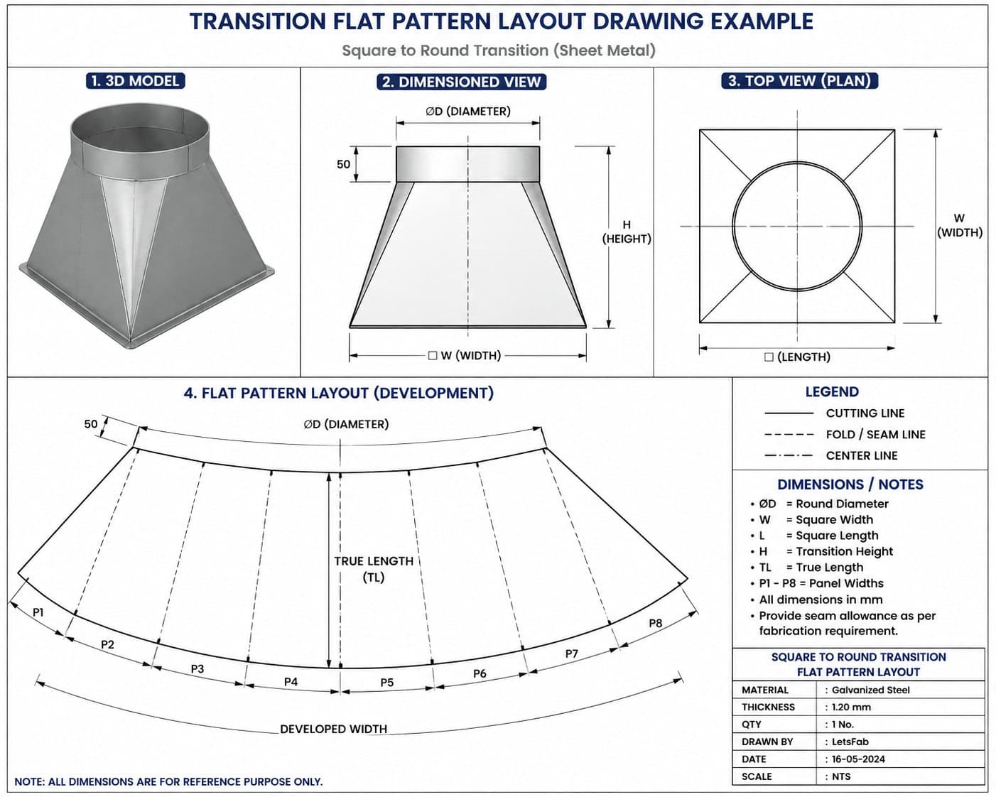
A transition flat pattern layout drawing is a two-dimensional representation of a three-dimensional transition component.
The drawing shows the developed shape before bending, rolling, or assembly and provides all dimensions necessary for fabrication.
A flat pattern drawing typically includes:
- Development profile
- True length dimensions
- Reference points
- Bend lines
- Seam allowances
- Material dimensions
- Section labels
- Fabrication notes
The drawing acts as the manufacturing blueprint for the transition.
Why Are Flat Pattern Drawings Important?
Accurate flat pattern drawings help ensure:
- Correct material cutting
- Proper fit-up during assembly
- Reduced fabrication errors
- Lower material wastage
- Improved production efficiency
- Consistent fabrication quality
Without a proper development drawing, fabricators often rely on trial-and-error methods that increase costs and production time.
Components of a Transition Layout Drawing
Development Profile
The development profile represents the unfolded shape of the transition.
This is the actual cutting pattern used during fabrication.
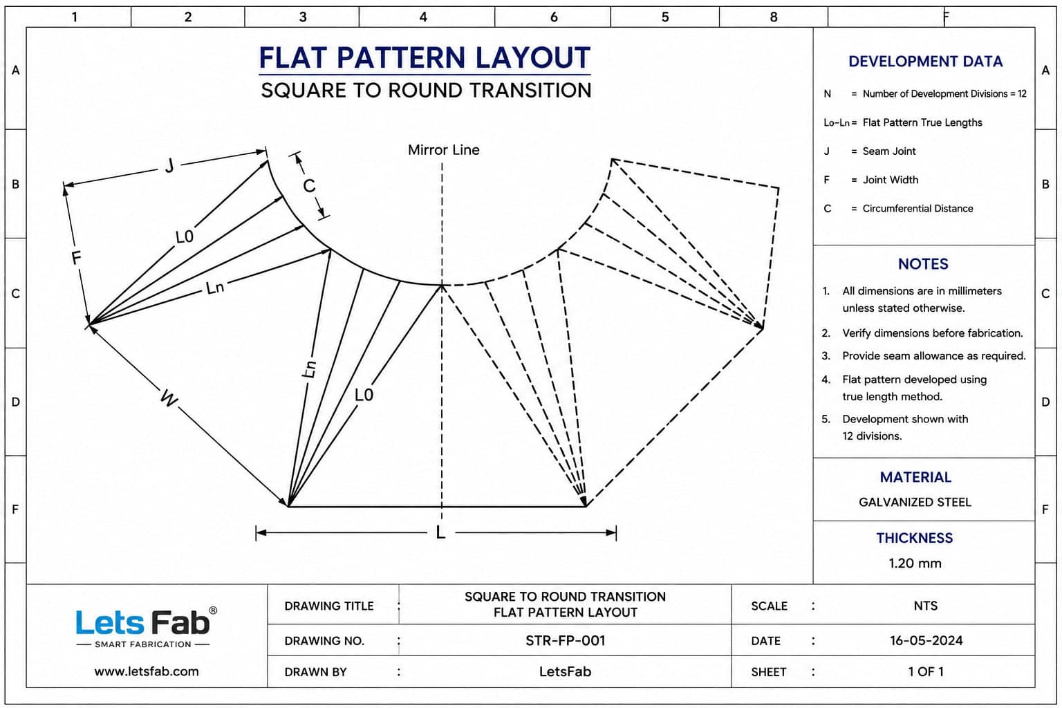
True Length Lines
True length lines define the actual distances along sloping surfaces.
These dimensions are essential for creating accurate layouts.
Reference Points
Reference points help transfer dimensions from calculations to the sheet material.
They ensure accurate marking and alignment.
Bend and Forming Lines
Where required, bend lines indicate locations where forming operations must occur.
Seam Allowances
Additional material may be included for welding, riveting, lock forming, or joining methods.
Information Commonly Shown on Flat Pattern Drawings
A complete transition drawing may contain:
- Overall dimensions
- Diameter dimensions
- Width dimensions
- Length dimensions
- Height dimensions
- Material thickness
- Part identification
- Quantity information
- Development dimensions
- Fabrication instructions
How Transition Layout Drawings Are Created
The typical workflow includes:
Step 1 – Define Geometry
Identify:
- Round dimensions
- Square dimensions
- Height
- Offset dimensions
Step 2 – Calculate Development Dimensions
Use:
- True length calculations
- Triangulation methods
- Radial development methods
- CAD development tools
Step 3 – Generate Flat Pattern
Convert the 3D geometry into a 2D layout.
Step 4 – Add Fabrication Information
Include dimensions, labels, seam allowances, and manufacturing notes.
Step 5 – Transfer to Production
Use the drawing for:
- Manual layout
- CNC plasma cutting
- Laser cutting
- Waterjet cutting
- Fabrication operations
Common Types of Transition Drawings
Square to Round Transition Drawings
Used for HVAC duct systems and industrial ventilation equipment.
Round to Square Transition Drawings
Used where circular equipment must connect to square ductwork.
Pyramid Transition Drawings
Used for hoppers, chutes, and industrial transitions.
Truncated Pyramid Drawings
Used in material handling and process industries.
Manual Drawings vs CAD-Generated Layouts
Traditional workshop drawings were produced manually using drafting methods.
Today many fabricators use:
- AutoCAD
- SolidWorks
- Inventor
- Sheet metal software
- Transition Development Calculators
Benefits of digital layouts include:
- Improved accuracy
- Faster revisions
- Reduced drafting time
- Better manufacturing consistency
Common Errors in Transition Drawings
Common mistakes include:
- Incorrect true lengths
- Missing dimensions
- Wrong development points
- Improper seam allowance calculations
- Incorrect scaling
- Missing fabrication notes
Careful verification helps avoid costly workshop errors.
Benefits of Using a Transition Development Calculator
Modern Transition Development Calculators automatically generate accurate development dimensions and fabrication layouts.
Benefits include:
- Faster calculations
- Improved drawing accuracy
- Reduced manual drafting
- Consistent results
- Reduced material waste
These tools simplify the process of creating fabrication-ready transition drawings.
Try the free Transition Development Calculator
Explore Let’sFab Premium Software
Industries Using Transition Layout Drawings
Transition development drawings are widely used in:
- HVAC Fabrication
- Industrial Ventilation
- Dust Collection Systems
- Cement Plants
- Power Plants
- Material Handling Equipment
- Process Equipment Manufacturing
- Sheet Metal Fabrication Workshops
Frequently Asked Questions
What is a flat pattern layout drawing?
A flat pattern layout drawing is a developed two-dimensional shape used to manufacture a three-dimensional sheet metal component.
Why are true lengths important?
True lengths ensure that the fabricated component matches the intended geometry after forming and assembly.
Can transition drawings be created manually?
Yes. Traditional drafting methods are still used, although modern software and calculators significantly improve efficiency.
What information should be included in a transition drawing?
Dimensions, development profiles, reference points, fabrication notes, seam allowances, and material specifications should all be included.
Related Resources
- How to Calculate Transition Development
- Square to Round Transition Development
- Round To Square Transition Development
- Pyramid Transition Development
- Truncated Pyramid Transition Development
- Transition Development Calculator
- LetsFab Premium Flat Pattern Calculator
- Free Sheet Metal Development eBook
Conclusion
Transition flat pattern layout drawings are a critical part of sheet metal fabrication. They transform calculated development dimensions into practical fabrication instructions that can be used for cutting, forming, and assembly.
Whether created manually or generated using modern software tools, accurate development drawings improve fabrication quality, reduce waste, and streamline manufacturing operations.