Eccentric Cone Development for Sheet Metal Fabrication
Eccentric cone development is a specialized flat pattern calculation used when the centerlines of two circular openings are intentionally offset. Unlike a concentric cone, where both diameters share the same centerline, an eccentric cone creates a transition between offset openings.
Eccentric cone developments are commonly used in process plants, industrial ducting, piping systems, dust collection equipment, and material handling applications. Because of their complex geometry, accurate flat pattern generation is essential for successful fabrication.
In this guide, you’ll learn what an eccentric cone is, where it is used, the dimensions required for development, and how modern software can generate accurate layouts quickly and efficiently.
What Is an Eccentric Cone?
An eccentric cone is a conical transition where the top and bottom diameters do not share the same center point.
Unlike a concentric cone:
- Centerlines are offset
- Surface lengths vary around the perimeter
- Development geometry becomes more complex
- Flat pattern calculations require true-length methods
Because of these characteristics, eccentric cones are more challenging to develop manually.
An eccentric cone may also be referred to as:
- Offset Cone
- Eccentric Reducer
- Offset Reducer
- Eccentric Cone Layout
- Eccentric Flat Pattern
Where Are Eccentric Cones Used?
Eccentric cone developments are commonly used in:
- Industrial piping systems
- Dust collection systems
- Material conveying equipment
- Process plants
- HVAC systems
- Industrial exhaust systems
- Cyclone separators
- Fabricated reducers
- Equipment transitions
These applications often require custom dimensions and offset arrangements.
Dimensions Required for Eccentric Cone Development
Most eccentric cone developments require:
- Large Diameter
- Small Diameter
- Height
- Offset Distance
- Material Thickness (if compensation is required)
These values define the geometry required to generate the flat pattern.
Understanding Eccentric Cone Geometry
The geometry of an eccentric cone is significantly different from a concentric cone.
Because the centerlines are offset:
- True lengths vary around the perimeter
- Pattern boundaries become irregular
- Different generator lines have different lengths
- Accurate calculations become more important
Traditional fabrication methods often require dividing the cone into multiple segments and calculating true lengths individually.
For a general overview of cone geometry, see our Cone Development Guide.
For the formulas behind cone development calculations, see our Cone Development Formula guide.
Manual Eccentric Cone Development Method
Traditionally, fabricators create eccentric cone developments using triangulation and true-length methods.
The typical process involves:
- Defining diameters and offset.
- Dividing the cone into equal segments.
- Calculating true lengths.
- Constructing the development curve.
- Generating the final pattern layout.
Although effective, manual methods can be time-consuming and prone to error.
Example of Eccentric Cone Development
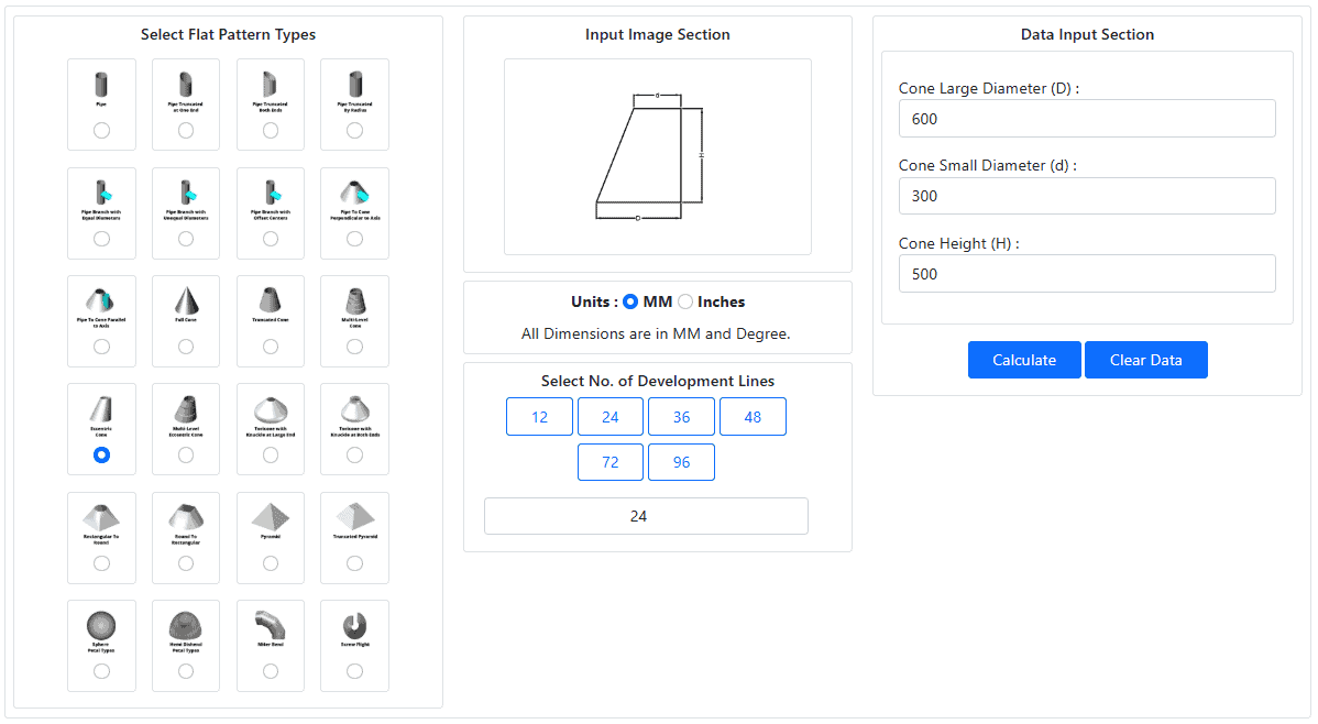
Consider an eccentric reducer with:
- Large Diameter: 600 mm
- Small Diameter: 300 mm
- Height: 500 mm
- No. of Development Lines: 24 Nos.
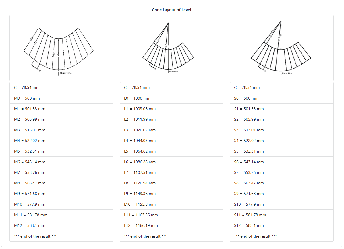
Using these dimensions, an accurate flat pattern can be generated for fabrication.
The workflow typically includes:
- Entering dimensions.
- Generating the development.
- Reviewing calculated geometry.
- Exporting fabrication-ready outputs.
Need DXF export, professional PDF reports, fractional dimensions, and access to all flat pattern calculators? Explore Let’sFab Premium.
Common Challenges
Fabricators frequently encounter:
- Incorrect true-length calculations
- Development curve errors
- Pattern scaling issues
- Offset calculation mistakes
- Repeated design revisions
Even small errors can create significant fit-up problems during fabrication.
Generate Eccentric Cone Flat Patterns Using Let’sFab
The Let’sFab Cone Development Calculator includes an Eccentric Cone option for generating accurate flat patterns.
Simply enter:
- Large Diameter
- Small Diameter
- Height
The calculator automatically generates:
- Developed pattern layout
- Manufacturing geometry
- PDF reports
- DXF export files (Premium)
- Fabrication-ready dimensions
This allows fabricators to generate accurate layouts within seconds.
Try the free Cone Development Calculator
Explore Let’sFab Premium Software
Why Use an Eccentric Cone Development Calculator?
Using a dedicated development calculator provides:
- Faster calculations
- Improved accuracy
- Reduced material waste
- Faster project revisions
- Consistent results
- Professional fabrication documentation
This is especially valuable when working with multiple custom reducer designs.
Need DXF export, professional PDF reports, fractional dimensions, and access to all flat pattern calculators? Explore Let’sFab Premium.
Frequently Asked Questions
What is an eccentric cone?
An eccentric cone is a conical transition where the top and bottom diameters have different centerlines.
What is an eccentric reducer?
An eccentric reducer is a fabricated component used to connect two different diameters while maintaining an offset between centerlines.
Why is eccentric cone development more difficult?
Because true lengths vary around the cone surface, the flat pattern geometry is more complex than a concentric cone.
What dimensions are required?
Most eccentric cone developments require large diameter, small diameter, height, and offset distance.
Can eccentric cones be developed manually?
Yes, but manual methods are often time-consuming and require detailed true-length calculations.
Related Resources
- How to Calculate Cone Development
- Cone Development Formula
- Cone Development Example
- Full Cone Development
- Truncated Cone Development
- Cone Development Calculator
- LetsFab Premium FlatPattern Software
Conclusion
Eccentric cone development is an important flat pattern calculation used in piping, ducting, and industrial fabrication projects. Because of the complex geometry involved, accurate development calculations are critical for successful fabrication.
Modern software tools can automate these calculations and generate fabrication-ready flat patterns within seconds, helping fabricators improve accuracy and reduce development time.